Pro 3

Arm Bar 150 150 Chris Scott

Arm Bar

Arm Bar

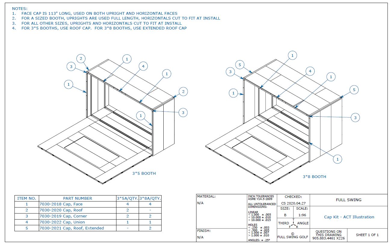
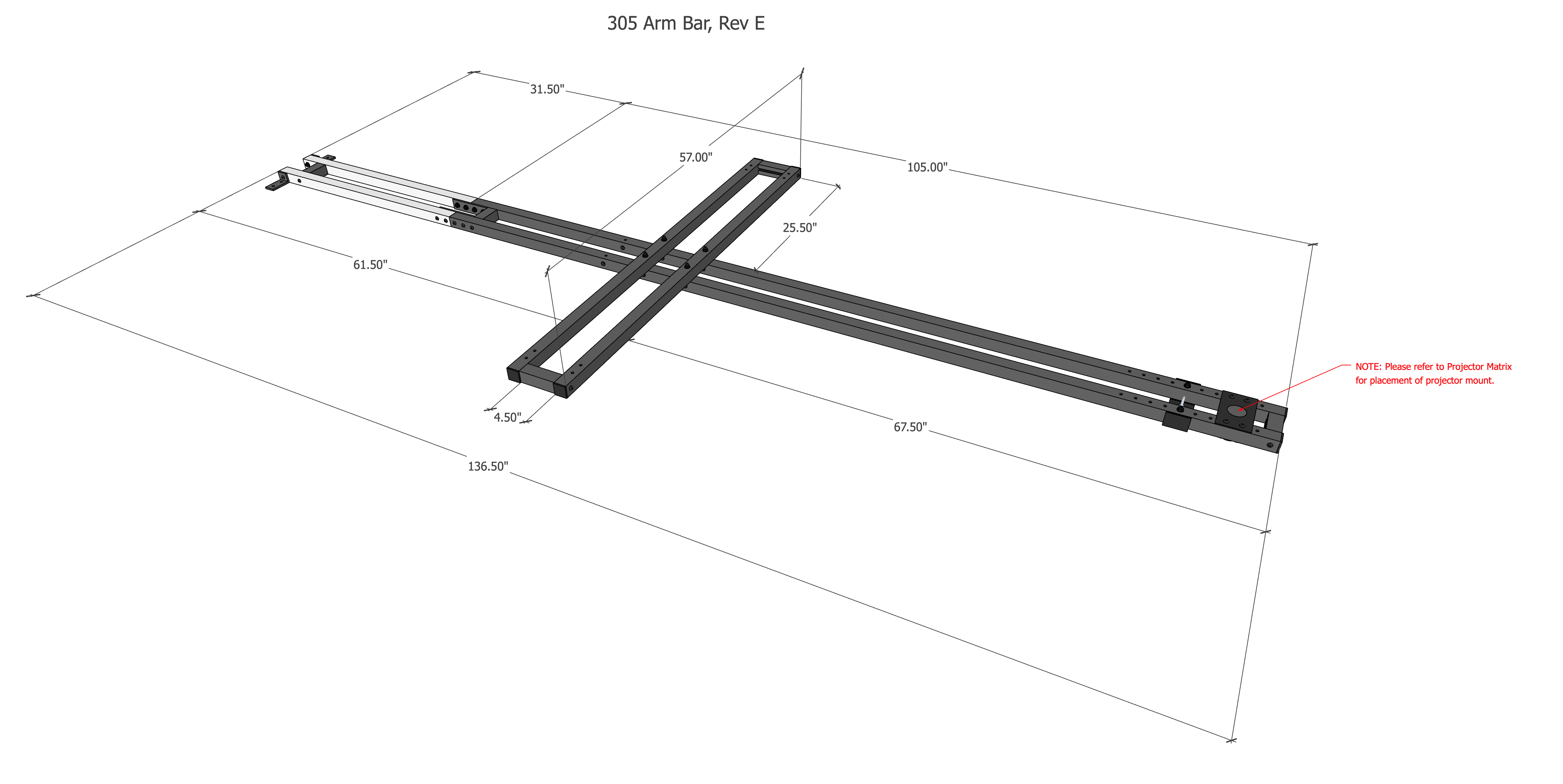
Arm Bar Illustration

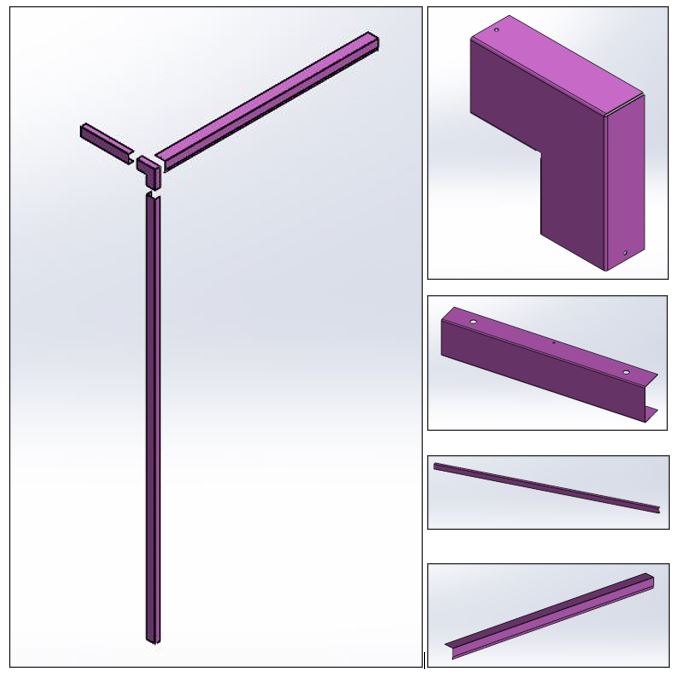
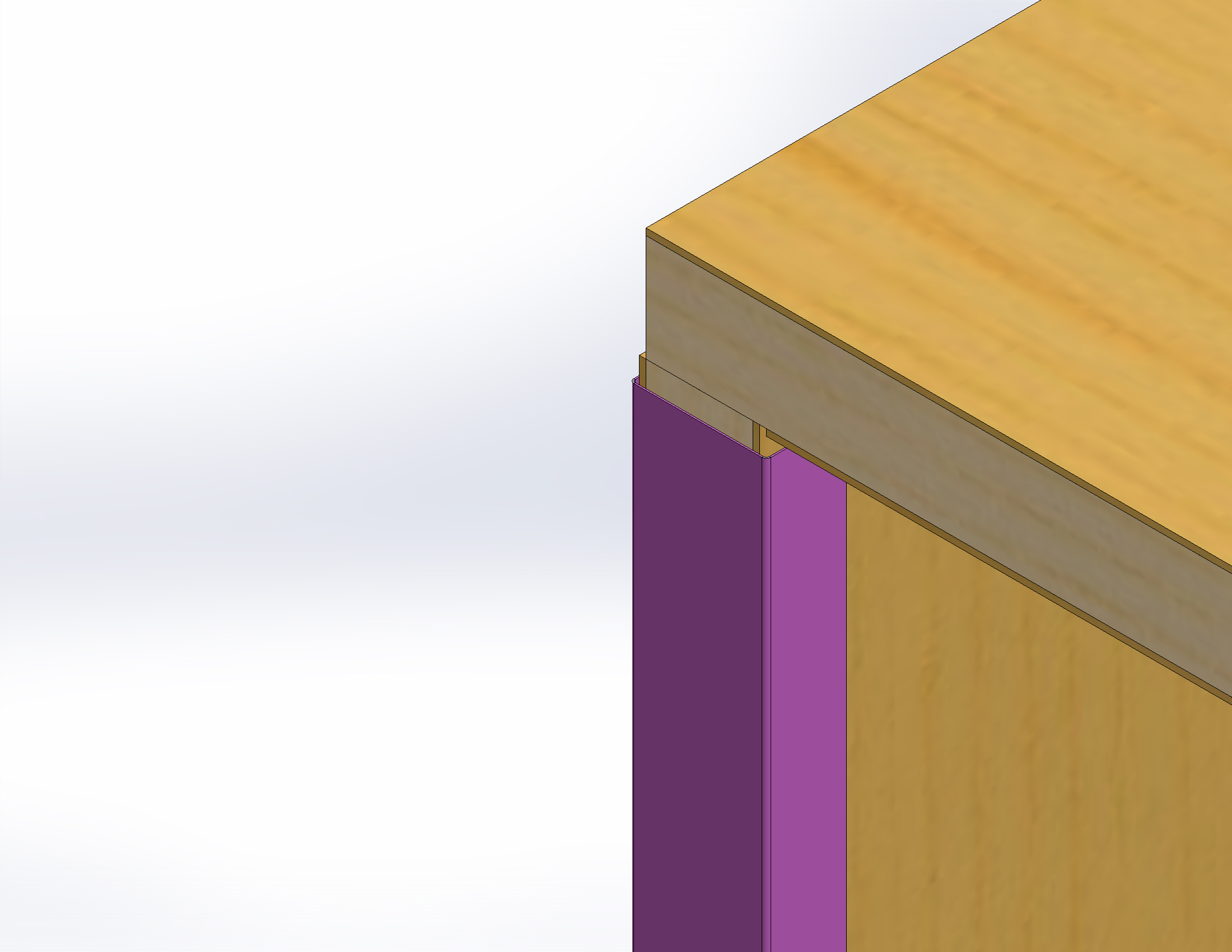
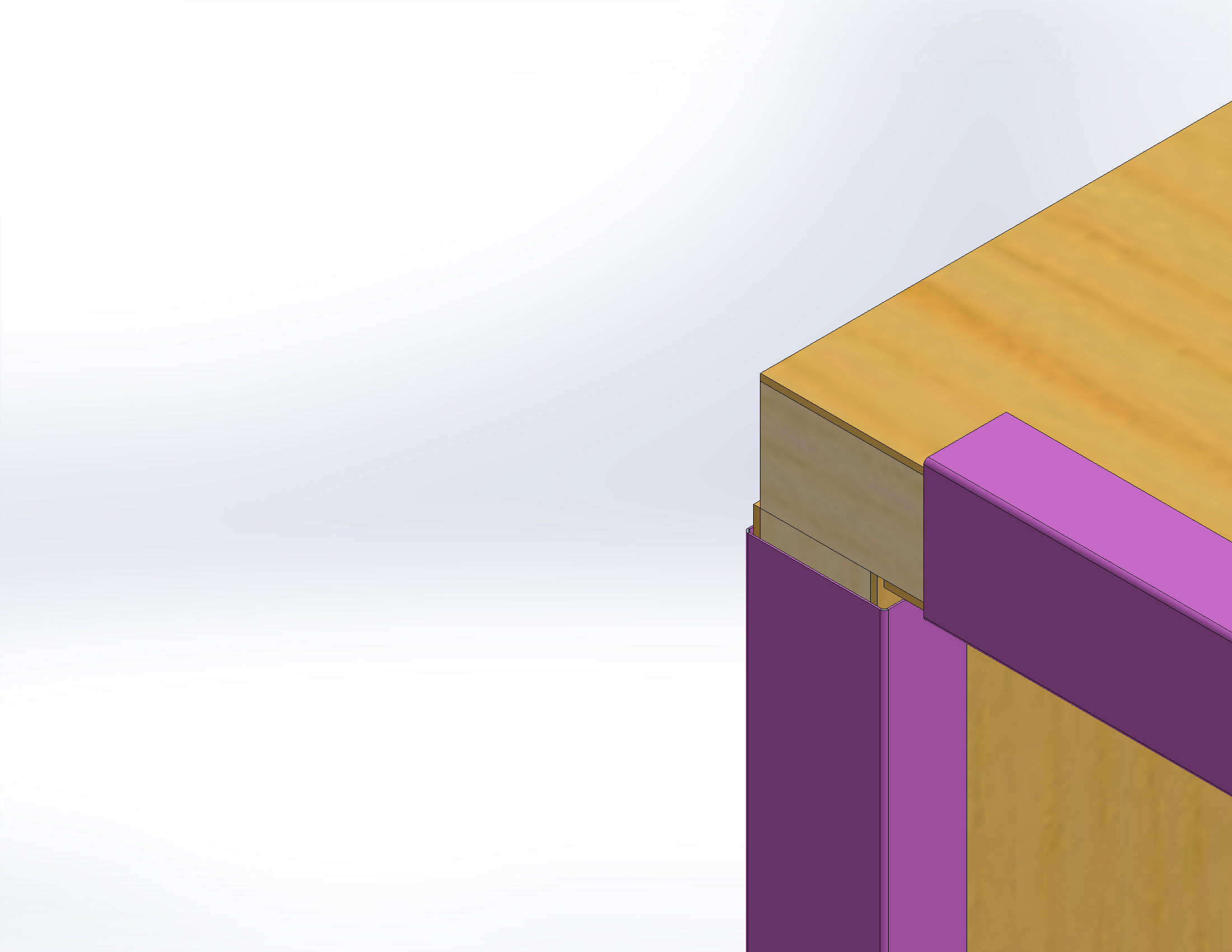
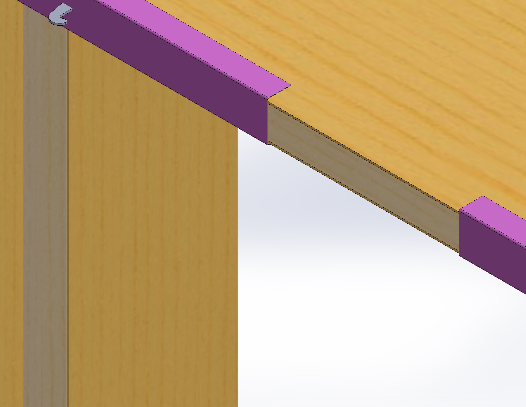
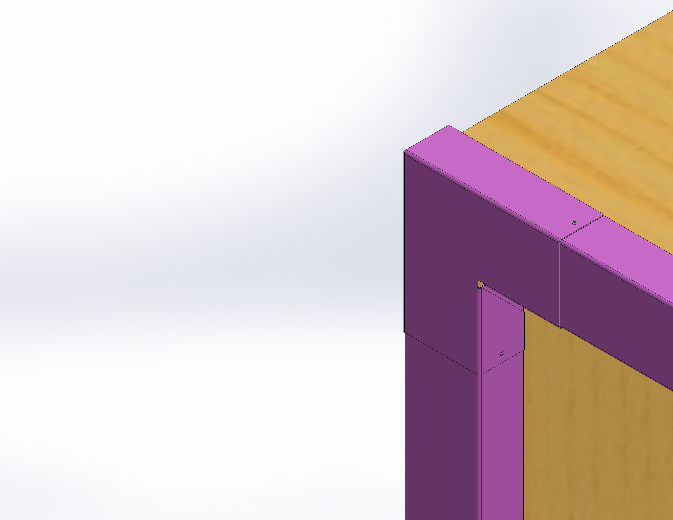
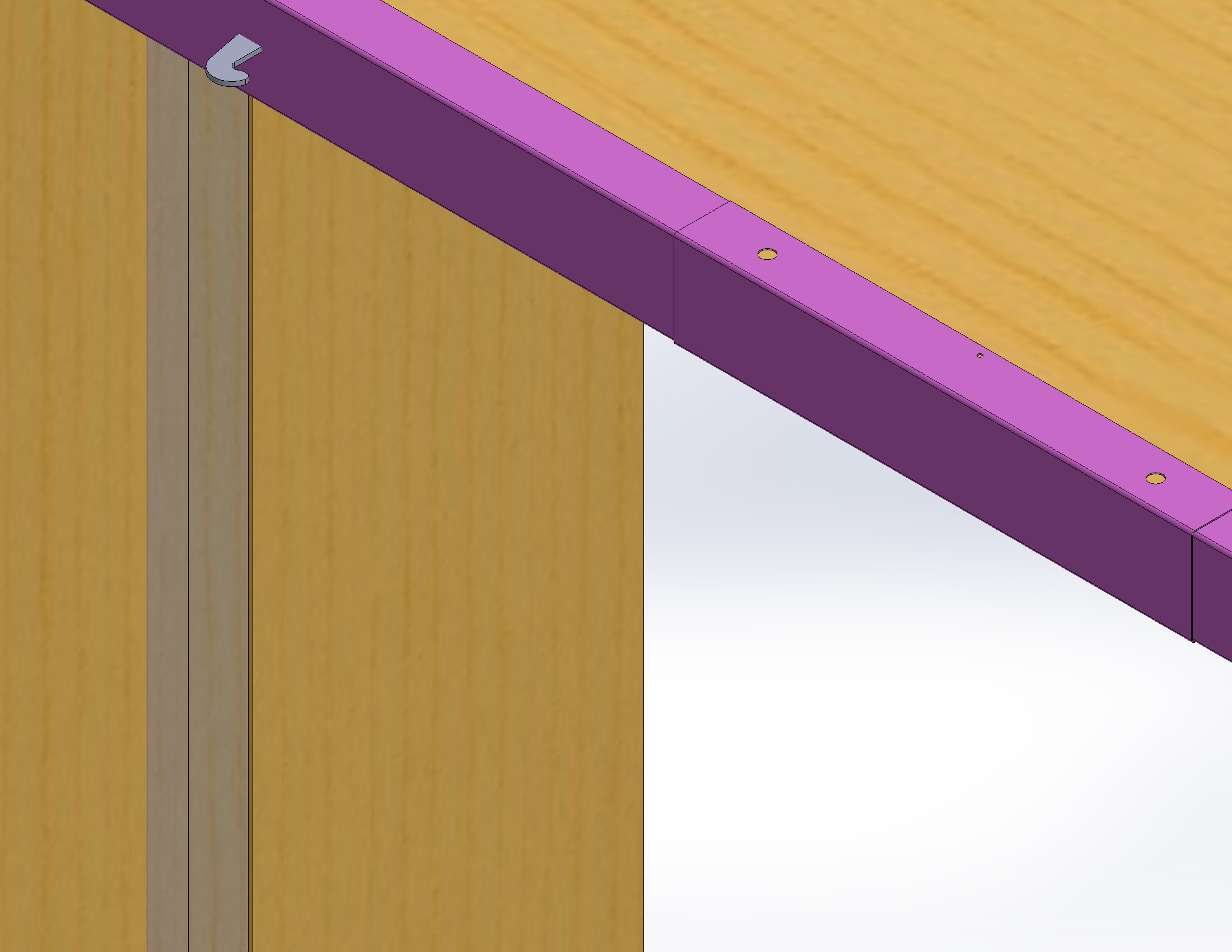
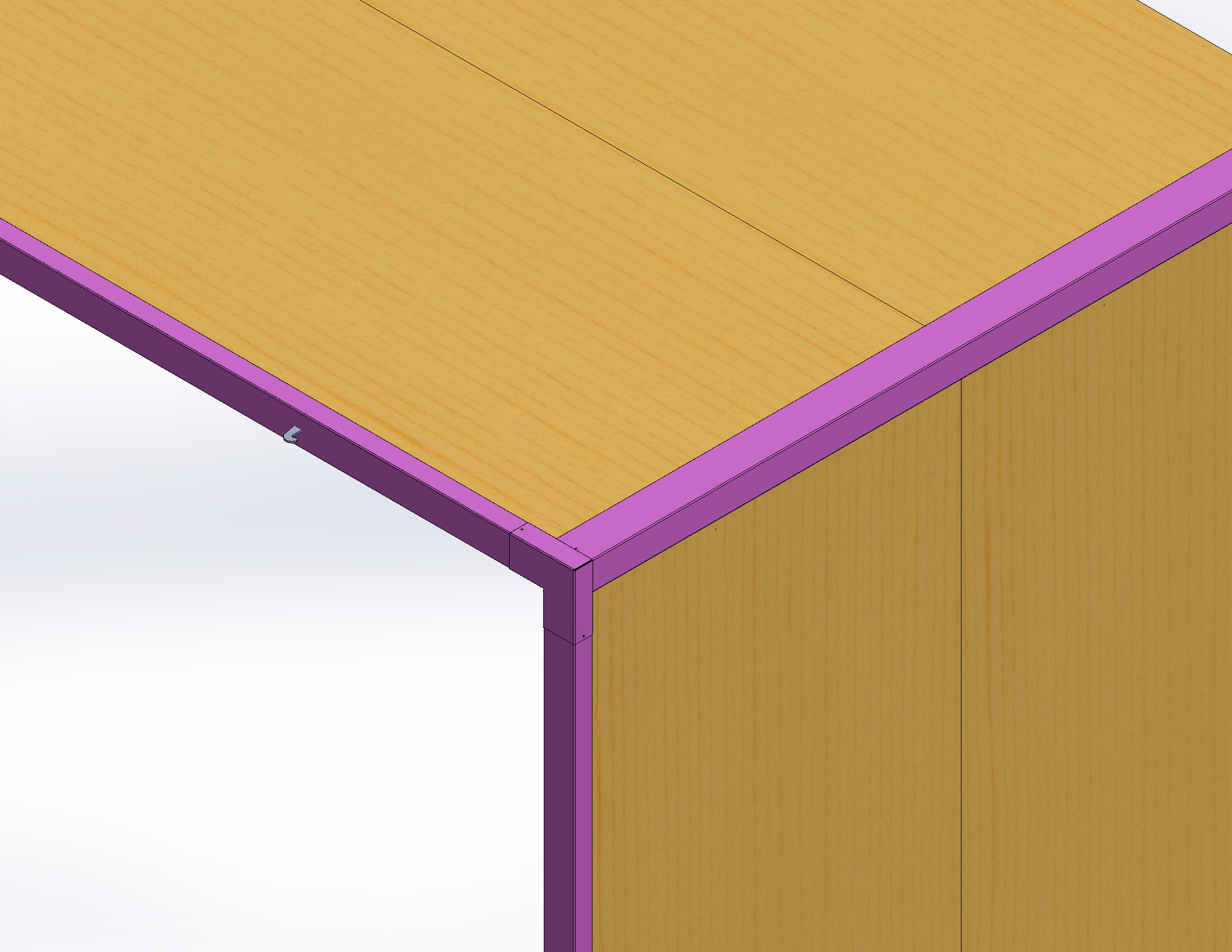
See below for an illustration of an assembled arm bar.  Take note of the dimensions for correct placement of the ION3 mounting bars.

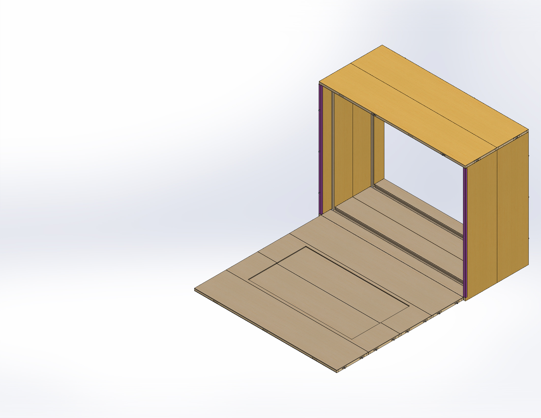
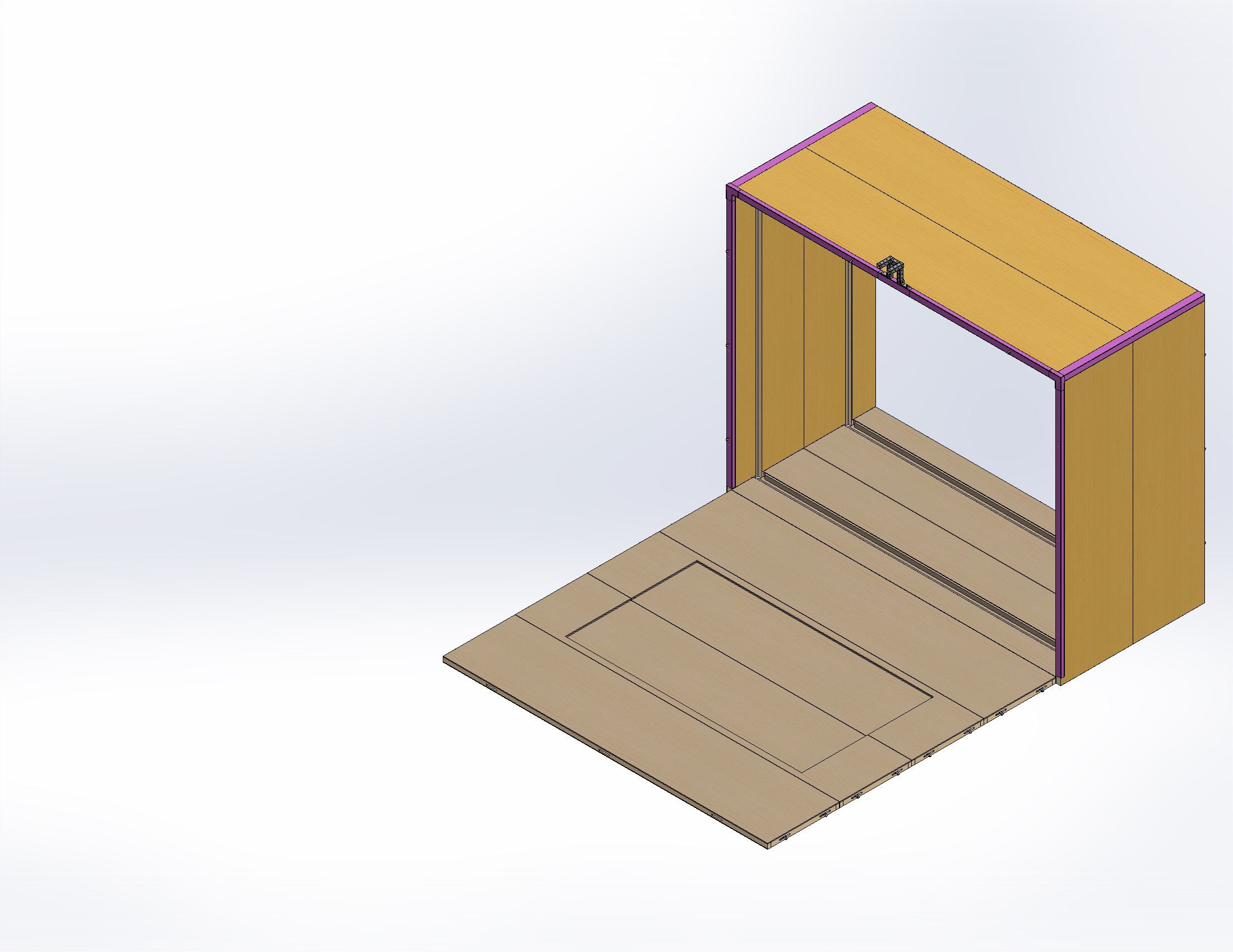
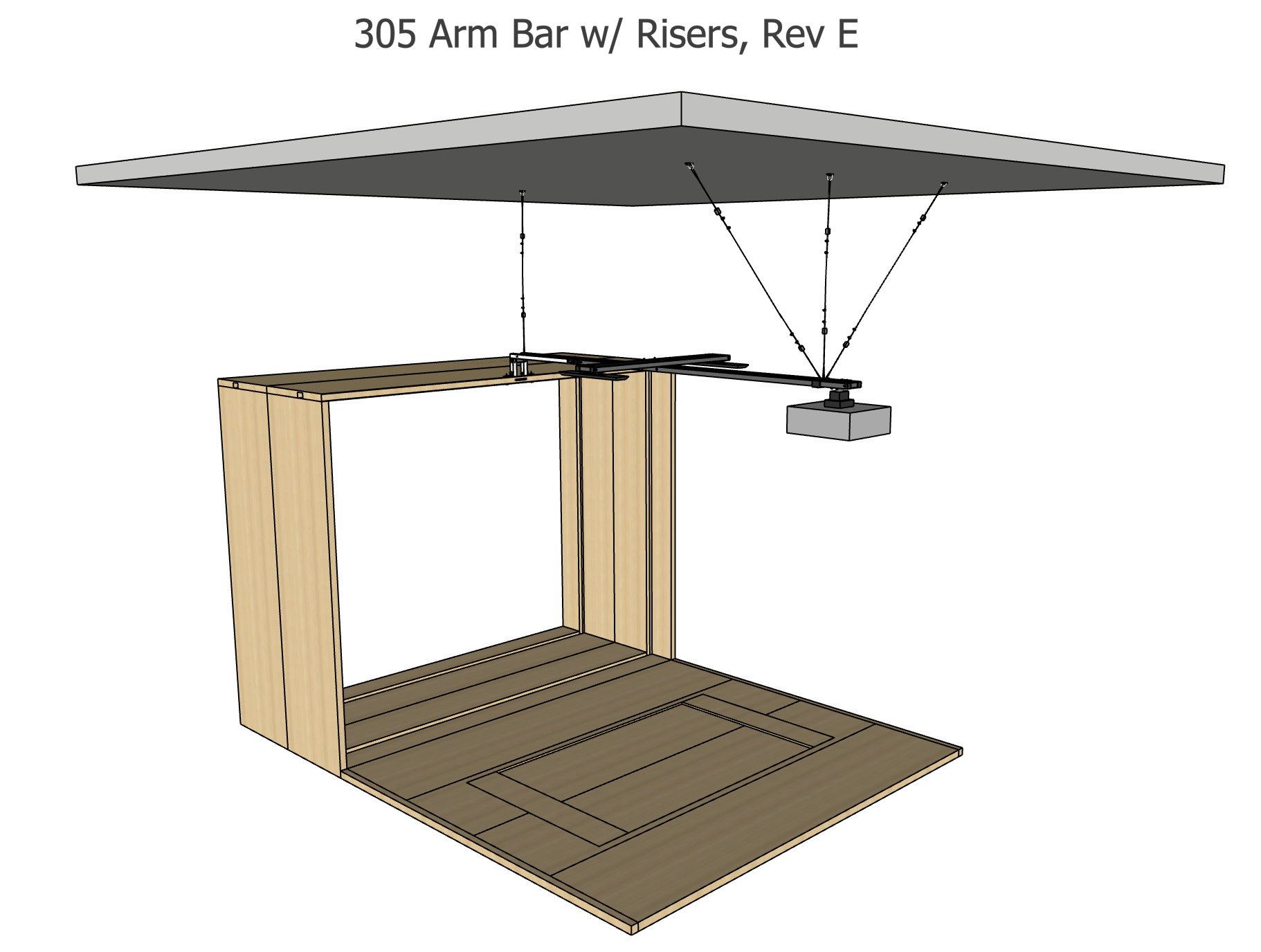
Below is an image of a complete arm bar installation with 4 safety cables in place.

Arm Bar Mounting Instructions

PARTS USED

Ceiling Attachment:
(1) Arm Bar Saddle
(4) D-Ring Anchors
(8) 1/4″ x 2″ Construction Lag Screws (for wood ceilings)
(8) 1/4″ x 1.75″ Tapcon Screws (for concrete ceilings)
(4) 20′ Wire Rope
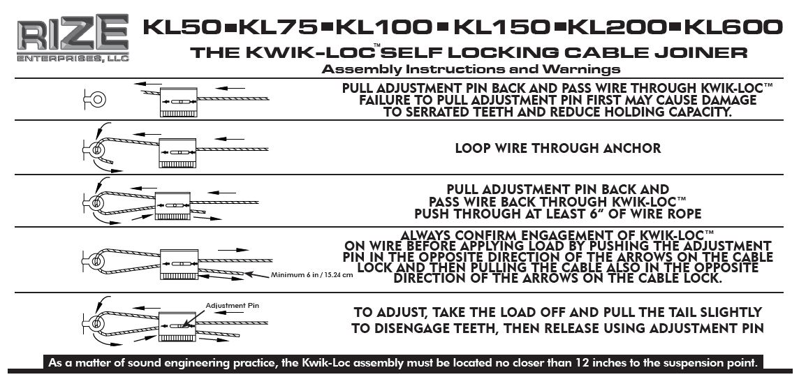
(8) Kwik-Loc wire rope locks
(16) Wire rope clamps

Booth Attachment:
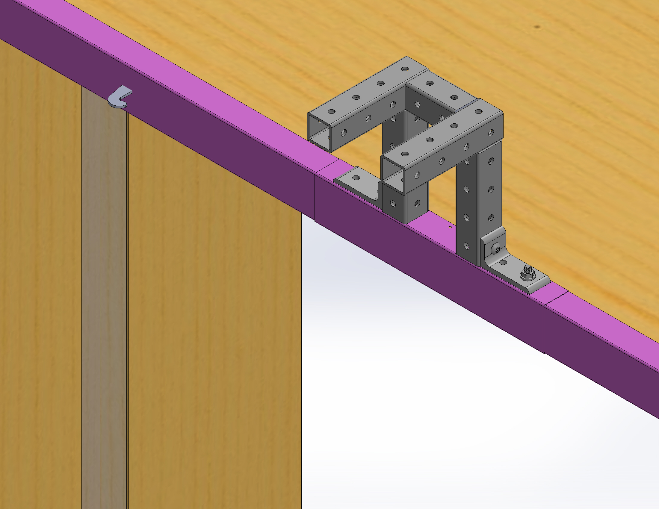
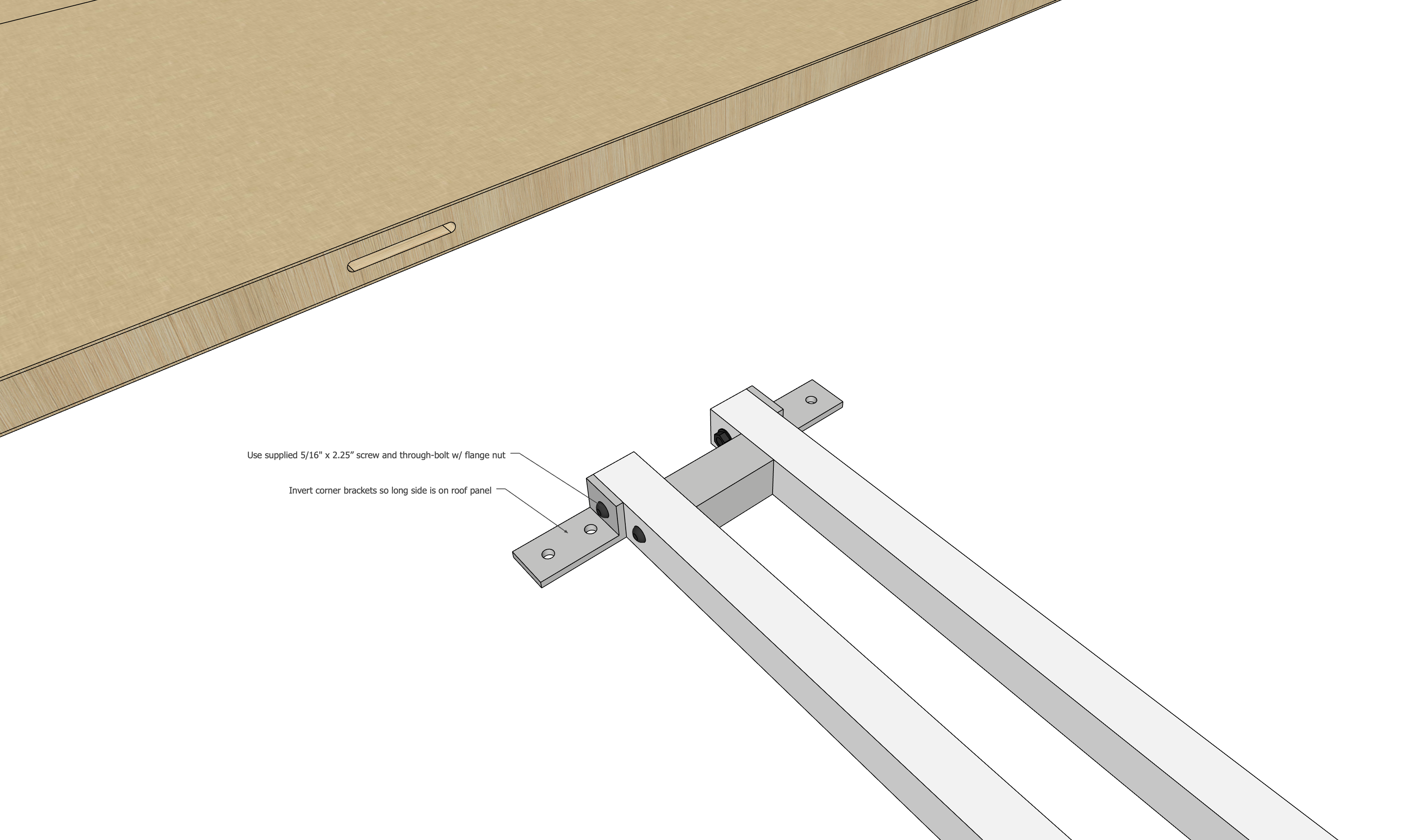
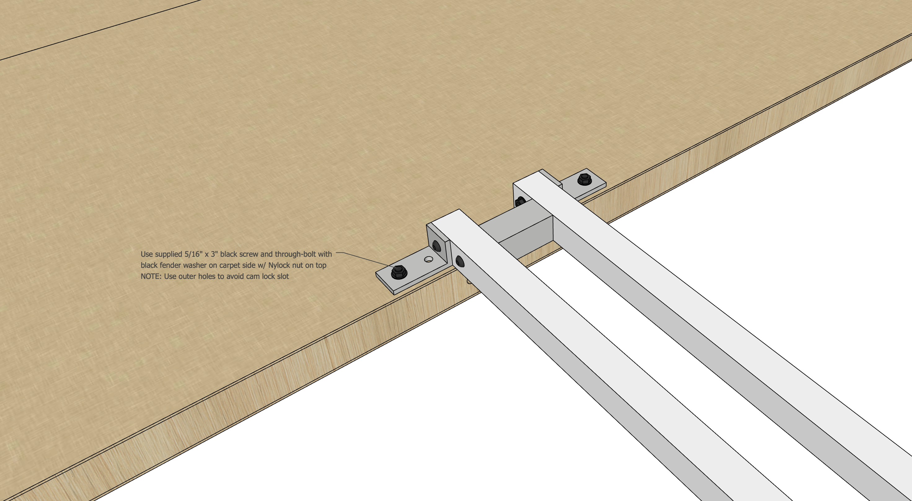
Fully Assembled Arm Bar
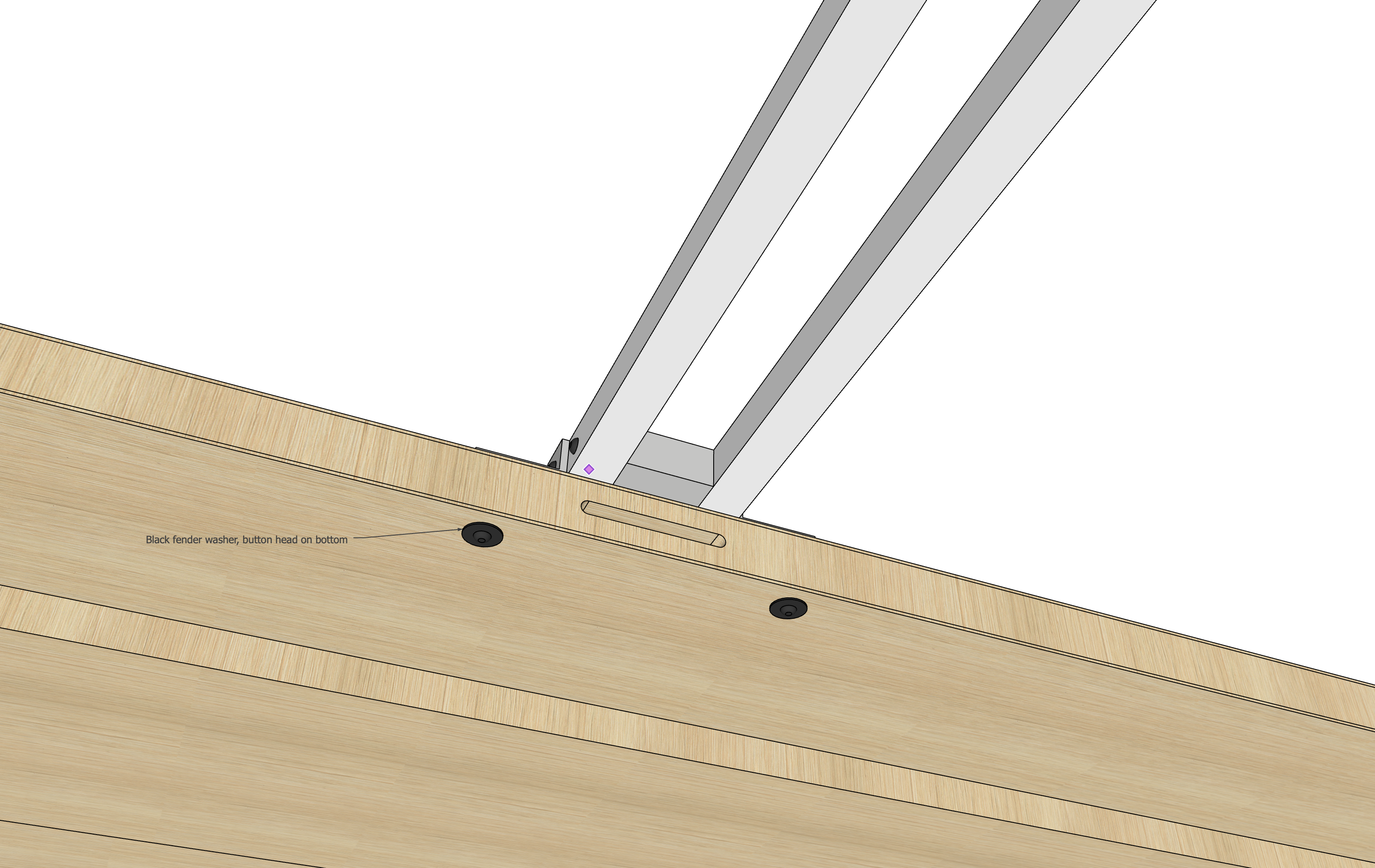
(2) 5/16″ x 3″ Button Head Socket Cap Screws (Black)
(2) 5/16″ x 1.25″ Fender Washers (Black)
(2) 5/16″ Nylock Nuts (Black)

Tools:
Impact Gun
Hammer Drill (for concrete)
3/16″ Hex bit
3/8″ deep socket (supplied)
1/4″ ratchet or drill adapter
11/32″ Drill Bit (supplied)
Wrench
Vise Grips or Channel Locks

Arm Bar Cables

Directions:

IMPORTANT: If you are retrofitting safety cables onto an armbar, remove projector from Arm Bar before attempting the retrofit.

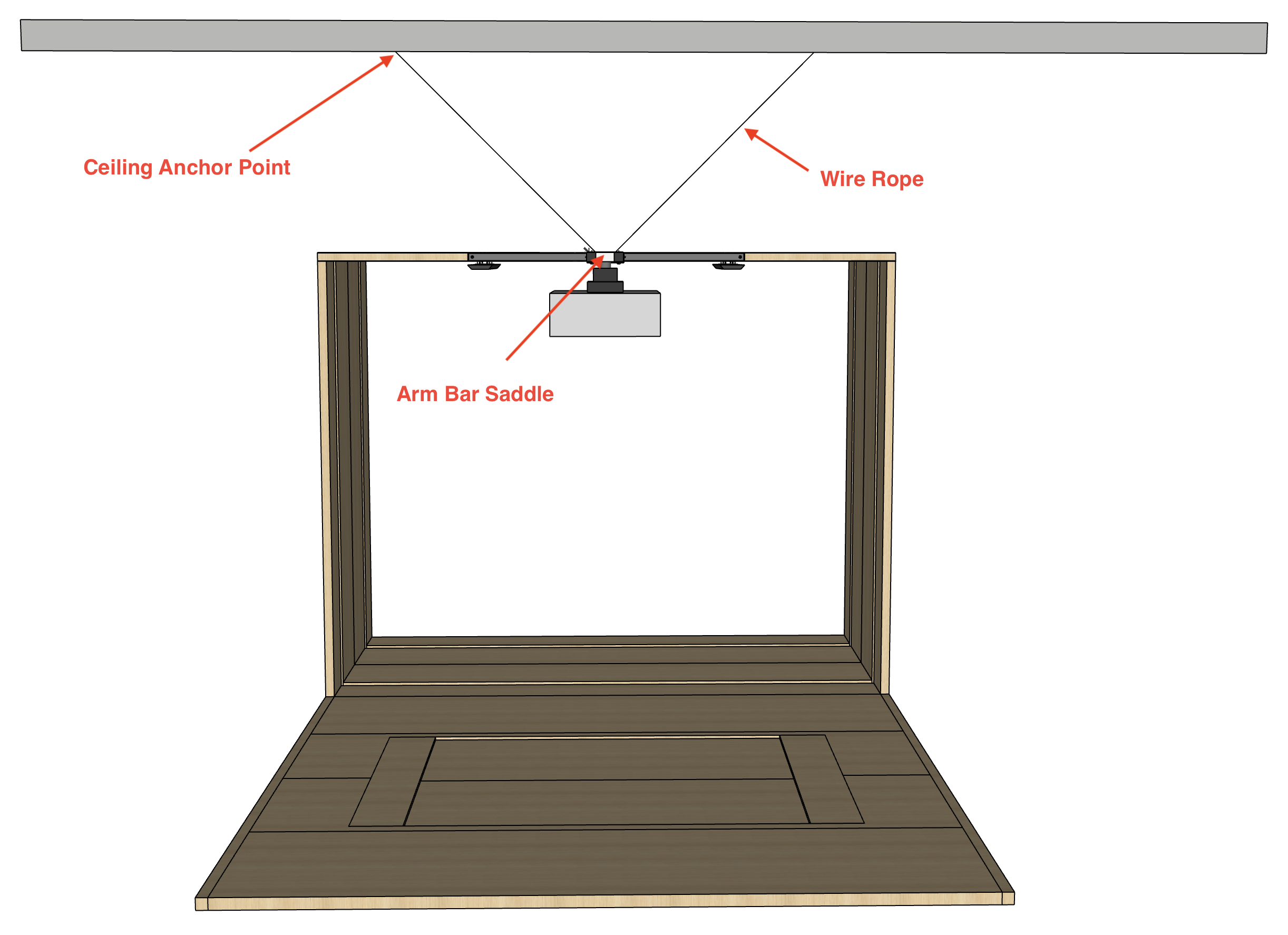
A finished Arm Bar installation will have four safety cables installed.  One at the simulator end going straight up, one at the projector end going straight up, and two in a V from the projector end.  Below are notes on installing the two V cables from the projector end.

1. Ensure all cables and Kwik-Loc devices are properly installed.

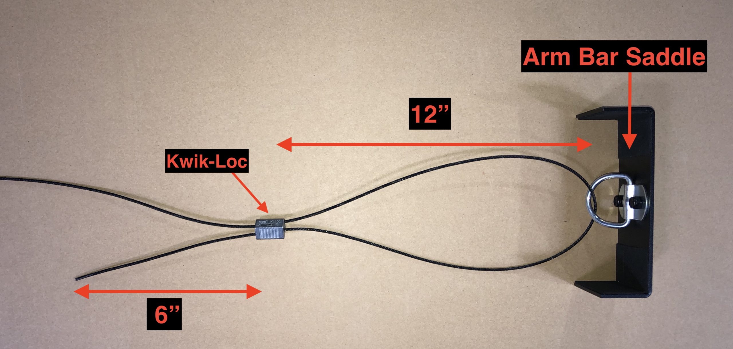
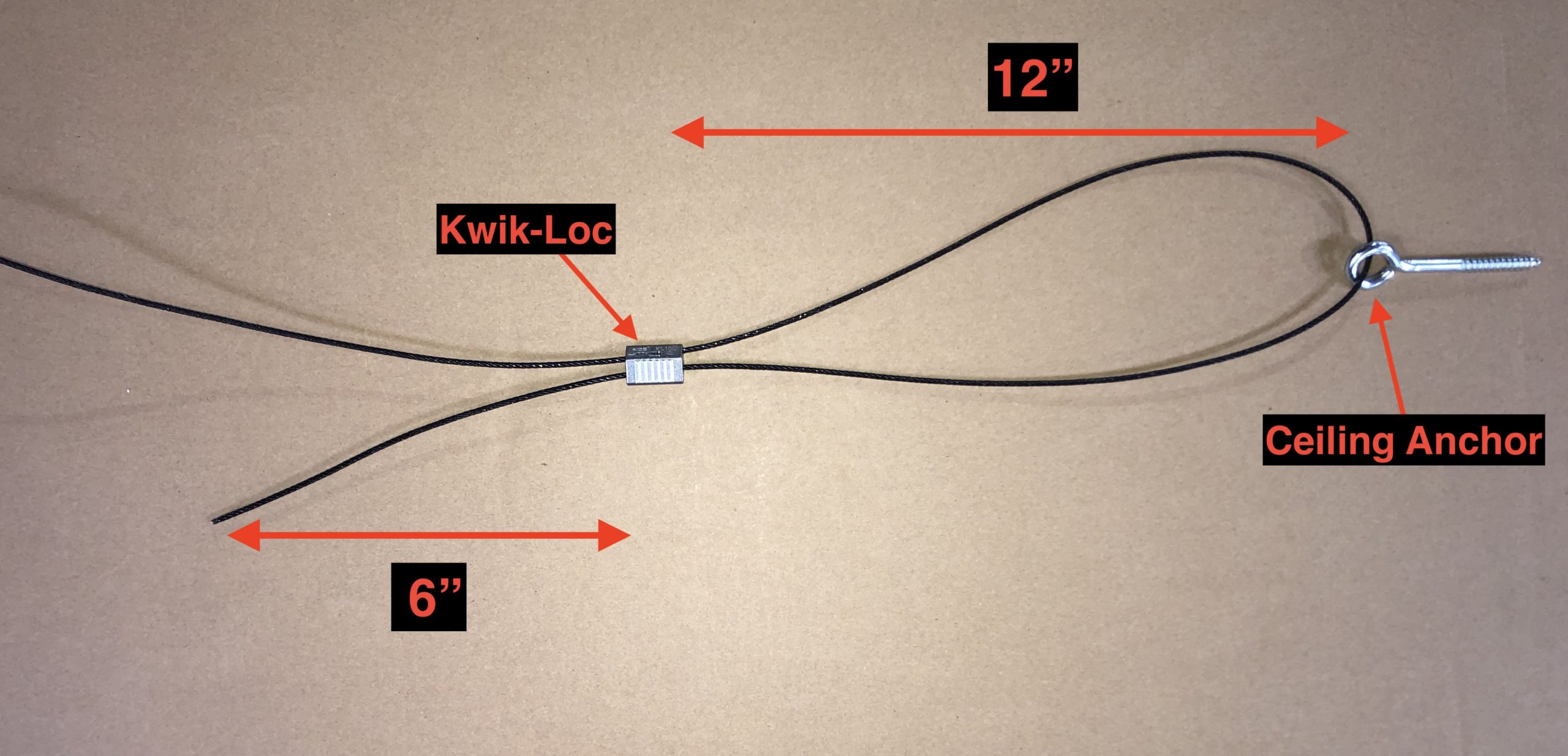
1A) Each Arm Bar should have two independent cables in a 45 degree “V” pattern. Each cable should be attached to an anchor point on the ceiling and attached to the Arm Bar Saddle as shown below.

1B) Each Kwik-Loc device should be 12” away from any anchor points or saddle and have at least a 6” tail coming out the back of the Kwik-Loc.

Please refer to Kwik-Loc’s instructions for proper installation and engagement of the Kwik-Loc device (attached at end of document).

NOTE: If cables are not properly installed and cannot be corrected onsite, please contact Full Swing for further direction.

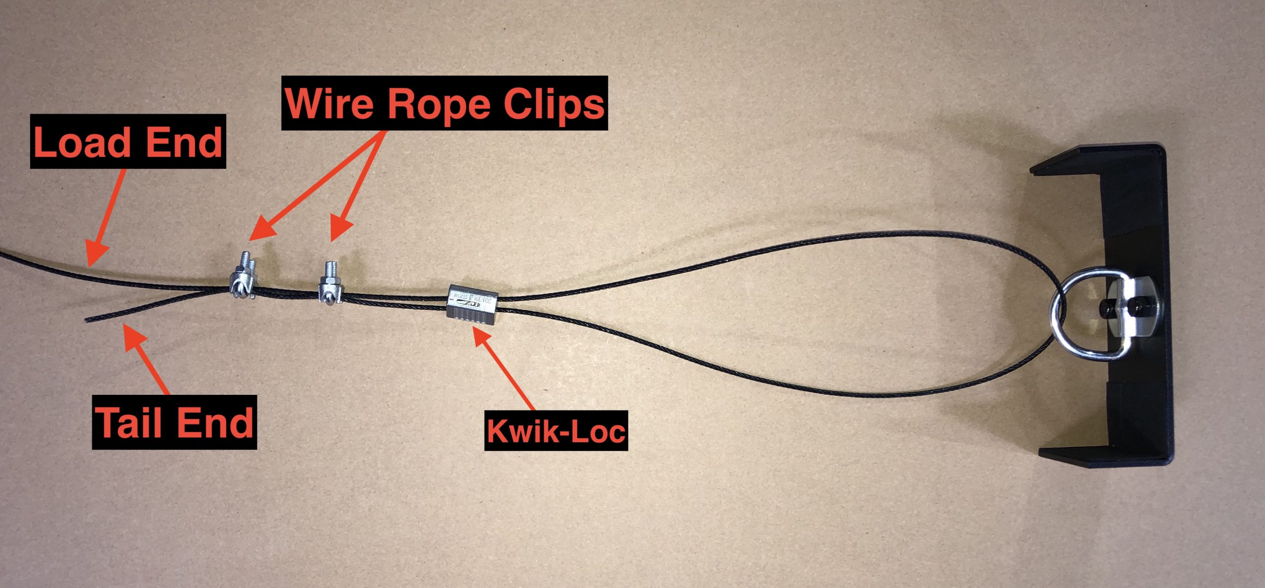
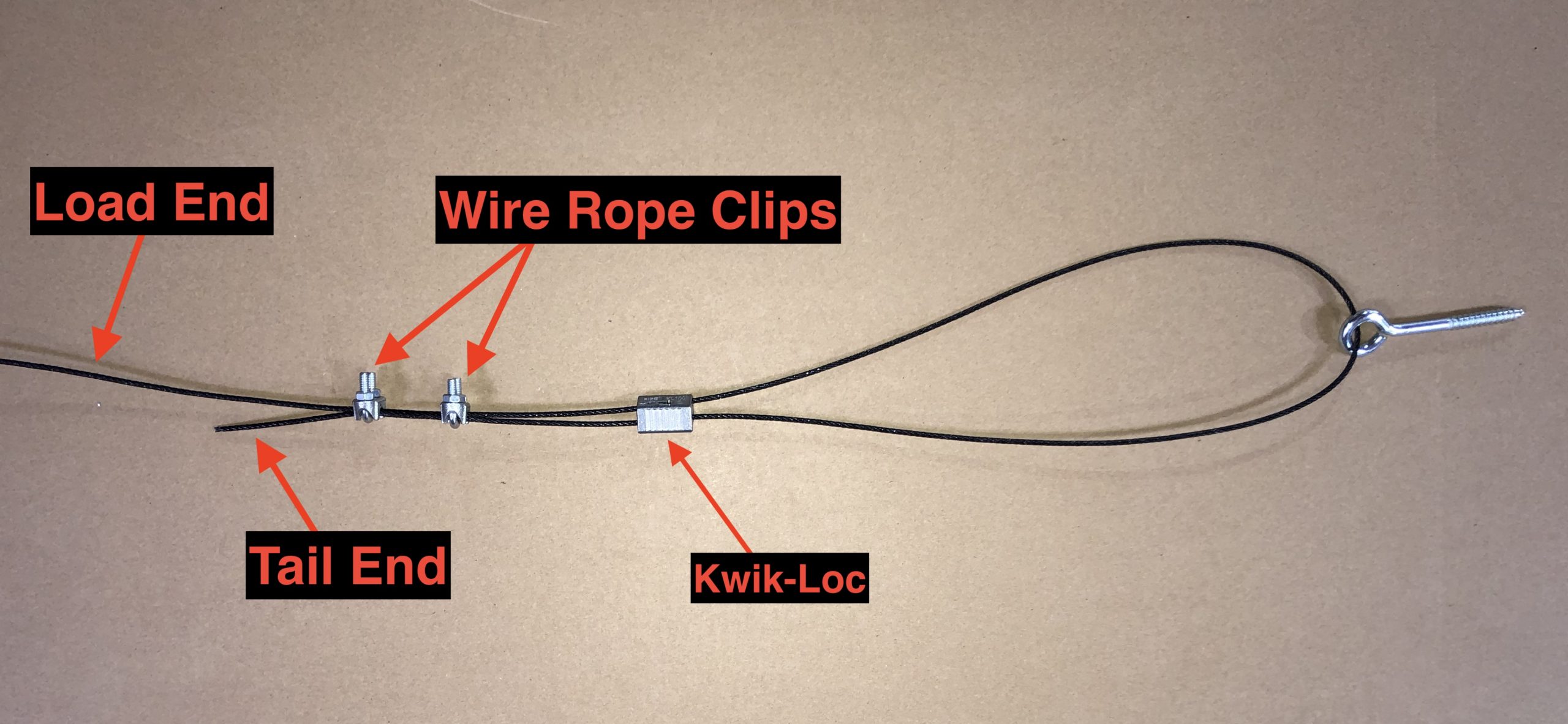
2) Install two wire rope clips on tail end of each Kwik-Loc device.

2A) Space the wire rope clips about 3” apart and install clips so that the base is on the long (live) end and the U-bolt is on the short (tail) end as shown below.

Every safety cable end should have this same configuration – 2 wire rope clips and a Kwik-Loc device.  So with a total of 4 cables with 2 ends each, you will repeat this configuration 8 times.

2B) Use Vise-Grips or pliers to hold the rope clip and tighten the nuts on the wire rope clip with the 3/8” socket. The nuts should be tight enough to keep the cable from slipping but please be careful to avoid damaging the cable.

Cap Kit 150 150 Chris Scott

Cap Kit

Series 3 Booth Cap Kit

There is a new cap kit to go along with the new series 3 booth design, and there are a few changes from the traditional cap kit.  The new kit is a smooth, flat black as compared to the traditional gloss wrinkled finish.

The new kit also includes pre-made corner pieces & union pieces.  This will reduce the amount of cutting required and provide a way to hide cut edges.

There are five different pieces: Corner, Union, Face, Roof, and Extended Roof.

See below for the general layout of the cap kit pieces:

Step 1

Place two FACE pieces on the wall faces.  Slide them down so they reach the floor.  On a full size A booth, you won’t need to cut the FACE pieces as they will be the correct length.  If you have a B or shorter sim, cut the top edge with shears so the FACE piece is a bit short of the roof.

Step 1
Booth with caps on wall faces
Step 1 Close Up
Cap piece near roof

Step 2

Place two FACE pieces on the roof face.  Place each FACE piece so one end is a bit short of the wall.  Then trim the other end of the FACE pieces so there is a 12″ gap in the center.

Step 2
Booth with caps on roof face
Step 2 Closeup A
Cap on roof face near wall
Step 2 Closeup B
12`` between caps on roof face

Step 3

Place two CORNER pieces in the upper left and right corners.  These are designed to slide over the FACE pieces on the wall & roof, hiding any cuts you had to make.  Secure the CORNER with double sided tape or self tapping screws using the holes provided.

Step 3
Corner pieces on booth
Step 3 Closeup
Corner piece in upper left corner of booth

Step 4

Place a UNION piece in the center of the roof face.  This piece should cover any cuts you needed to make to the FACE pieces.  The holes in the UNION can be used as hole guides if an arm bar needs to be installed.  The small hole in the center can be used for a self tapper.

Step 4
Union piece installed on roof face
Step 4 Closeup
Union piece covering face pieces in center of roof

Step 5

Place two ROOF pieces along the two sides of the wall/roof interface.  The ‘wiper’ should be facing down, and the ROOF piece can be pushed up against the CORNER piece.

Step 5
Booth with roof pieces installed
Step 5 Closeup
Closeup view of roof piece on upper right corner of booth

Step 6

If an arm bar is installed, use the pre-drilled holes in the UNION as a guide for installing the arm bar.

Step 6
Booth with arm bar installed
Step 6 Closeup
Closeup of arm bar detail installed through union cap piece

END OF NOTE

Gen 3 Floor Carpet 150 150 Chris Scott

Gen 3 Floor Carpet

Gen 3 Booth Floor Carpet

Install the floor carpet using the 2 rolls supplied and the guide below.

Pro 3 Baffles 150 150 Chris Scott

Pro 3 Baffles

Pro 3 Baffle Installation

1. Installation Orientation

Use the illustration below to install the ceiling baffles in the correct location & orientation.

Note that all baffles are longer than required, and will need to be cut to fit the booth width.  Use shears to make straight, vertical cuts to the baffles.  Cutting the baffles ‘freehand’ with a blade can yield poor results (crooked cuts).

Below is a top view of the baffle installation on a Sport booth. This illustrates how the baffle length needs to be trimmed to fit the width of the booth correctly.

Isometric View:

Widescreen Roof Panel Assembly (Sport/Pro 3) 1024 678 Brian Farley

Widescreen Roof Panel Assembly (Sport/Pro 3)

Widescreen Roof Panel Assembly (Sport/Pro 3)

The roof panels for the Sport/Pro 3 Widescreen booths require a new installation method to help reinforce the entire roof. Please read these directions thoroughly before you begin installing the roof.

1. Parts used

  • 3″ drywall screws
  • 2″ x 28″ Top Bridge w/ cam locks (detail below)

2. Remove Shipping Inserts

Remove the shipping inserts from the end of roof panels. These are taped in place to protect Lauan plywood during shipment.

BE CAREFUL NOT TO DAMAGE THE THIN PLYWOOD EDGES AFTER REMOVAL!!!

3. Lock Roof Panels Together

A. Orient panels with interior facing up

B. Lock short and long panels together

4. Screw Bridges Across Both Roof Panels

A. Orient Bridge Rails as shown in diagram.
NOTE: Make sure hooks and pins are in the correct locations!

B. Screw bridges across seam of both panels using (6) 3″ drywall screws.
NOTE: You must pre-drill six holes to avoid splitting the bridge pieces!

Click here to view full PDF diagram

Diagram of two assembled roof panels.

Click here to view full PDF diagram

4. Install Roof Panels as Normal

Install roof panels as you normally would on widescreen sims.

NOTE: You must secure roof panels to customer ceiling to prevent sagging. More instructions to follow shortly.

Pro 3: Booth Diagrams 1024 781 Brian Farley

Pro 3: Booth Diagrams

Save the 11″ x 58.5″ plywood pieces that are packed with the booth. These must be installed in the hitting mat recess to reduce the width to 83″ as shown in the diagrams below.

WIDESCREEN ROOF PANEL ASSEMBLY: The roof panels for the Sport/Pro 3 Widescreen booths require a new installation method to help reinforce the entire roof. Please click here for detailed instructions.